Solving beam deflection problems using the moment-deflection approach and using the Euler-Bernoulli approach
by Nasser M. Abbasi
November 2009
Links
PDF file
Mathematica notebook
Introduction
These are problems in beam deflection showing how to use Mathematica to solve them.
Problem 1
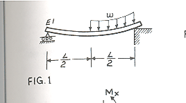
This is problem 9-3, page 551, from bok Problem Solvers, strength of materials and mechanics of materials by REA. I show here how to solve this problem using Mathematica.
Start by setting up the moment deflection equation for the Euler beam E I y''[x]=M(x) , this equation is found for both halves of the beam resulting in 2 solutions,  and
and  .
.
On the right side, boundary condition is that  and on the left side
  , then we need an additional 2 boundary conditions, for this, use the continuity conditions at L/2 where we set
  and
and  and now we have the complete solutions.
For the left half of beam, it is easily found that  and for the right half
Find 

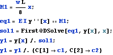

Use first boundary condition 


Find 
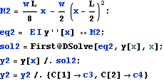

Use boundary condition 


We see from the above, that we have 2 additional constants of integrations to solve for. c2 and c4. To solve for these, we use the continuity conditions at L/2


All the integration of constants now found, we can now plot moment diagrams, shear diagram, and deflection diagrams


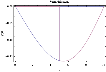
Assign some values for E, I, L and w and do the plots. PLot the deflection

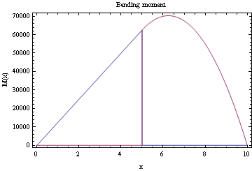
Plot the bending moment

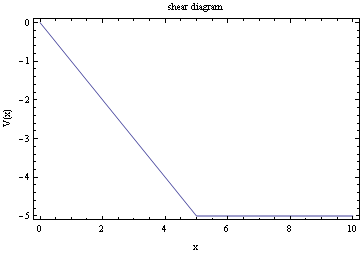
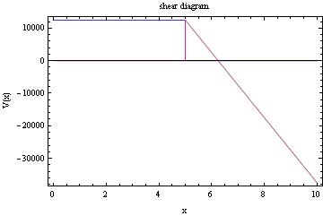
Plot the shear diagram

Solving the same problem directly from the Euler-Bernoulli  order ODE
The above approach (using the Moment-deflection ODE) is a standard approach to solve deflection beam problems. However, we can also use the 4th order Euler beam equation direclty as follows. One needs to make sure that the load on the RHS of this ODE is the load per unit length only, i.e. w in this problem. Notice the use of the unit step function since w only acts on half the beam.

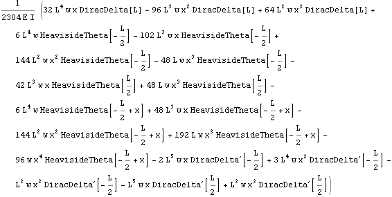
Assign some values for E, I, L and w and do the plots. PLot the deflection

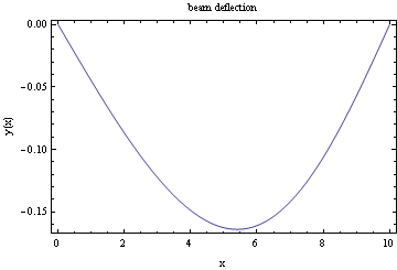
We see that we obtain the same result as earlier.
Plot the bending moment

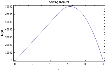
Plot the shear diagram

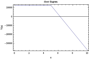
Problem 2
In this problem. I set up a cantilever beam and first solved it using the Java beam applet that can be accessed here
and then I solved this problem using Mathematica below, showing that I get the same answer as shown
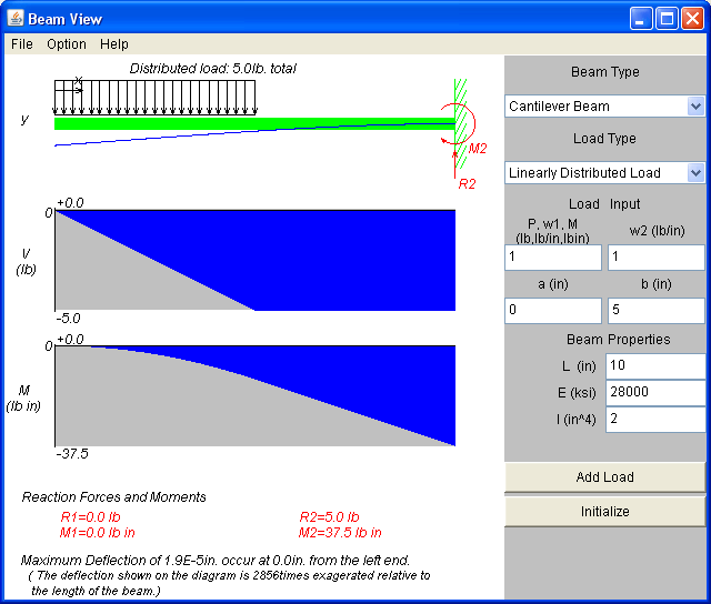

The boundary conditions to use are: y[L] == 0, y''[0] == 0, y'''[0] == 0, y'[L] == 0

Out[8]=

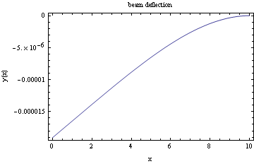
Assign same values as shown above for E, I, L and w and do the plots.
In[17]:=

Out[19]=

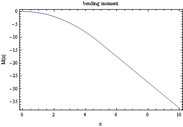
Plot the bending moment
In[23]:=

Out[23]=

Plot the shear diagram
In[25]:=

Out[25]=
