Disneyland ride final design report
Structural Dynamics Research Corporation (SDRC)
Daniel Belongia
Adam Mayer
Donny Kuettel
Nasser M. Abbasi
EMA 542 Advanced dynamics
University Of Wisconsin, Madison
Fall 2013
Dynamic analysis was completed for a new spinning ride as requested by Walt Disney Corporation.
Detailed derivation of model was completed for the main structural elements using rigid body dynamics.
Critical section was identified and maximum stress calculated to insure that the member does not fail
during operations and passengers acceleration does not exceed  g.
g.
Large software simulation program was completed to verify the model used and to allow selection of
optimal design parameters.
Prepared by:
Dynamic design team
Structural Dynamics Research Corporation (SDRC)
Contents
List of Figures
List of Tables
1 Introduction
A four-member team at Structural Dynamics Research Corporation (SDRC) has completed the final design for a
new spinning ride for Disneyland.
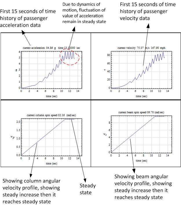
The ride features two non-collinear components of angular velocity. The head of each passenger will
experience a maximum of  acceleration. Just before this acceleration is reached, the ride will enter
steady state. During steady state, passengers will experience a small periodic fluctuation of acceleration
that ranges between
acceleration. Just before this acceleration is reached, the ride will enter
steady state. During steady state, passengers will experience a small periodic fluctuation of acceleration
that ranges between  and
and  but will not exceed
  . The ride can then enter the ramp down
phase and starts to decelerate until it stops with smooth landing. All three phases of the ride have been
simulated to insure the passengers will not exceed
. The ride can then enter the ramp down
phase and starts to decelerate until it stops with smooth landing. All three phases of the ride have been
simulated to insure the passengers will not exceed  during any of the phases. The ride is specifically
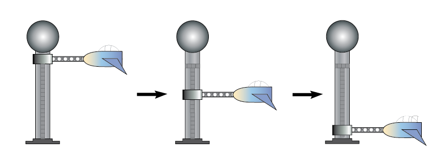
designed to be light, safe, affordable, and fun. The following is an artist rendering showing loading the
passengers in the cabinet before starting the ride
during any of the phases. The ride is specifically
designed to be light, safe, affordable, and fun. The following is an artist rendering showing loading the
passengers in the cabinet before starting the ride
Once the cabinet has reached the top of the support column, the ride will start. Extensive
simulation of the mathematical model of the dynamics of the model was performed to achieve an
optimal set of design parameters in order to meet the design goals as specified in the customer
requirements of a minimum weight and cost and at the same time insuring the structural members do
not fail and that the passengers will safely achieve the  acceleration in reasonable amount of time.
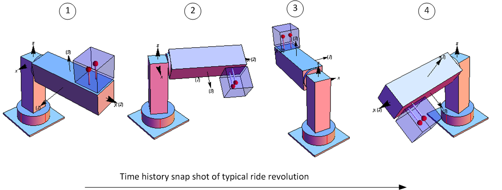
The conclusion section outlines the final design parameters found. The following diagram illustrates
typical one revolution ride for illustrations that was generated by the simulator developed specifically
for this design contract
acceleration in reasonable amount of time.
The conclusion section outlines the final design parameters found. The following diagram illustrates
typical one revolution ride for illustrations that was generated by the simulator developed specifically
for this design contract
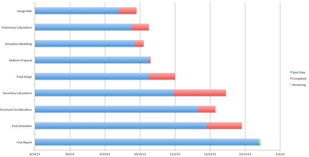
1.1 Gantt chart and history of design project
The design team followed the following timeline in the development of the report and the design. This is
illustrated below using Gantt chart
2 Safety considerations
The flight simulator will be equipped with multiple safety measures to ensure that passengers will have a fun and
exciting ride. In order to ride the flight simulator, each passenger must be at least  feet tall. This insures that
the riders can be securely fastened into the seat. Assuming an average rider weight of
feet tall. This insures that
the riders can be securely fastened into the seat. Assuming an average rider weight of  pounds, one single
rider cannot weigh more than
pounds, one single
rider cannot weigh more than  pounds.
Any more weight will induce a moment on the main arm that might be considered unsafe. A factor of safety
was factored into the building of the arm in case two riders combined weight to be more than  pounds. This additional weight accounts for the seating weight and the frame of the cabinet as
well.
pounds. This additional weight accounts for the seating weight and the frame of the cabinet as
well.
While the ride is in motion, each passenger will be harnessed into his or her seat via a 3-point harness. The
harness will let the passengers fly upside-down while still secured in the cockpit. Since the flight
simulator will be subject to  acceleration, complementary sick bags will be provided upon
starting.
acceleration, complementary sick bags will be provided upon
starting.
In case of a medical emergency of a passenger or if it has been determined that it is unsafe to
ride mid-flight, an emergency stop will be activated which will bring the ride to an end. When
activated, the ride will right itself upwards while bringing itself to a stop about the center of the
ride. This is so when the ride stops, the passengers are not hanging upside down which would be
unsafe.
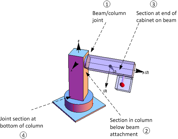
2.1 Locations of possible failure in the structure
Four critical sections in the structure were identified as possible failure sections. These are shown in the following
diagram. They ranked from  to
to  in order of possible first to fail. Hence section
  is the one expected to fail
first.
is the one expected to fail
first.
From bending moment diagram generated during initial runs of simulation it was clear that the bending
moment at section 1 was much larger than section 3. This agrees with typical cantilever beam model which the
above have very close similarity when considering the cabinet as additional distributed load on the beam.
However, this is a dynamic design and not static, hence time dependent bending moment and shear force
diagrams are used to validate this. These diagrams were not included in the final simulation software due to time
limitation to fully implement them in an acceptable manner. Due to also time limitations analysis for section 2
and 4 were not completed. The design team felt that protecting against failure in section 1 was the most
important part at this design stage as this is the most likely failure section. If awarded the design,
the team will include full analysis of all sections using finite element methods for most accurate
results.
3 Mathematical model of system dynamics
This section explains and shows the derivation of the mathematical model and dynamic equations. These
equations are used in the implementation of the software simulator in order to test and validate the design and
select the final optimal design parameters.
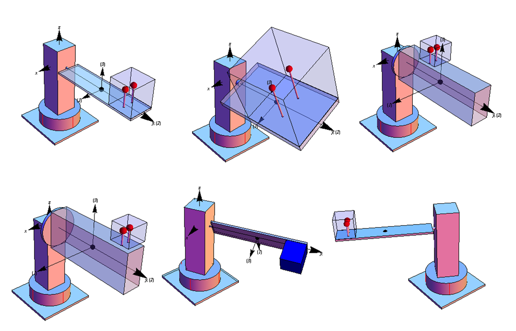
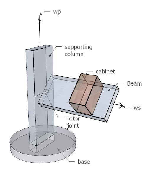
3.1 Review of the model structure used in the design
There are two rigid bodies: the beam and the supporting column. The cabinet is part of the beam but
was analyzed as a rigid body on its own in order to simplify the design by avoiding the determination of
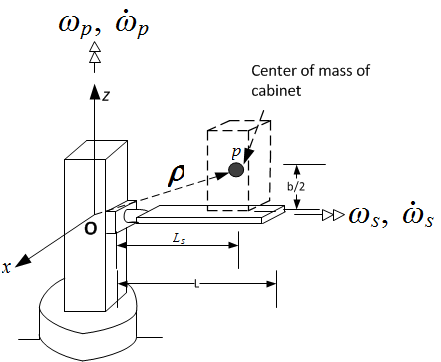
moments of inertia for a composite shaped body. The following architectural drawing shows the ride
structure.
The ride consists of the main support vertical column attached to a spinning base. Attached to one side of the
column is an aluminum beam connected to the column using a drive shaft coupling that allow
the beam to spin while attached to the column. A motor supplies the power needed to spin the
shaft.
The cabinet is mounted and welded on the beam. The location of the cabinet on the beam is a configurable
parameter in the design, and was adjusted during simulation to find an optimal location for the seating cabinet.
In final design the cabinet was located at the far end of the beam to achieve maximum passenger felt
acceleration.
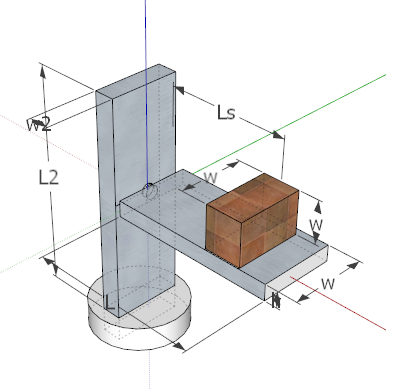
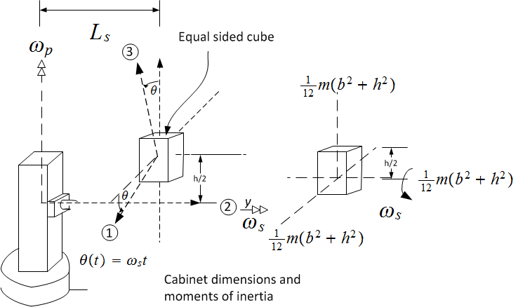
The passengers are modeled as one rigid body of an equal side solid cube of a mass that represents
the total mass of the passengers (maximum of 2 persons) with additional mass to account for the
seating weight and a factor of safety. The factor of safety was also an adjustable parameter in the
simulation. The following diagram shows the main dimensions of the structure used in the design.
3.2 Setting up the mathematical model
Euler rigid body dynamic equations of motion are used to determine the dynamic moments due to
the rotational motion of the rigid bodies. Principal Body axes, with its origin at the center of
mass of each rigid body was used as the local body fixed coordinates system. Newton method is
used to obtain the dynamics forces due to translation motion of the beam center of mass and
also the center of mass of the cabinet. The column has rotational motion only and no translation
motion.
After finding the dynamic forces, the unknown reaction forces at the joint between the beam and the column
are solved for. Since these forces are functions of time, simulation was required to check that they remain below
yield strength of Aluminium during the ride duration. Analytical solution is difficult due to the nonlinearity of
the equations of motion, but a numerical solution of the equations of motion would have been
possible.
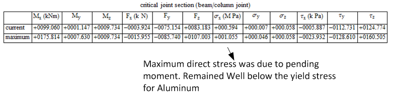
From beam bending moment diagrams generated for this design, the cross section at the beam/column joint
was determined to be the critical section. This is the section which will have the maximum bending moment as
well maximum shear force.
During simulation, the current values of the bending moment and shear force at the joint were tracked for
each time step taken. The maximum values of these are used to determine the corresponding
maximum stress concentration on the section to insure they do not reach  of yield strength of
Aluminum.
of yield strength of
Aluminum.  was used to protect against failure in shear which can occur before failure in
tension.
was used to protect against failure in shear which can occur before failure in
tension.
In order to minimize the number of parameters to vary in the design, the width of the cabinet was set to be
the same as the beam width. The stresses in the beam are calculated based on simple beam theory and
not plate theory. Due to time limitation, finite element analysis would was not performed. Finite
element analysis would give more accurate stress calculations which would have allowed the design
to be free to use less material by using thin plate for the platform and not thick beam as was
used.
The following is a summary of the main steps used in the dynamic analysis process
-
1.
- Break the system into 3 separate rigid bodies
-
2.
- Use Euler and Newton methods to determine dynamic loads on each body. Principal body fixed axes
are used with the reference point being the center of mass. (called case one analysis or
 ).
).
-
3.
- Draw free body diagram for each body and balance the dynamic loading found in the above step
in order to solve for unknown reaction forces.
-
4.
- Apply these reactions forces to the second rigid body connected to the first body by reversing the
sign on all vector. These new vectors now act as external loads on the second rigid body.
-
5.
- Perform Euler and Newton analysis on the second body to find its dynamic loads needed to cause
it motion.
-
6.
- Make free body diagram for the second body to balance the external forces with the dynamic loads
and remembering to use the loads found in step 3 as external loads to this second body.
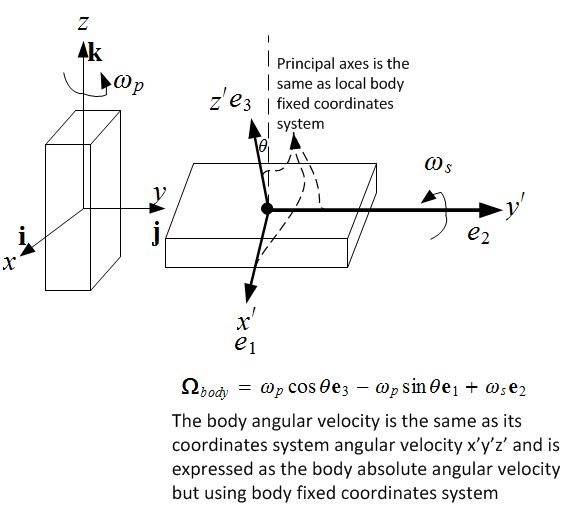
This diagram below illustrate the different coordinates axes used. The rotating coordinates system
that all forces and resolved for is the  . This has its origin at the joint between the beam and the
column. This coordinates system is attached to the column and rotates with the column at an absolute
angular velocity
. This has its origin at the joint between the beam and the
column. This coordinates system is attached to the column and rotates with the column at an absolute
angular velocity  . Each rigid body has its own local body fixed coordinates system
  . In this
design,
. In this
design,  have the origin at the center of mass of each rigid body and are aligned with the body
principal axes. Hence
have the origin at the center of mass of each rigid body and are aligned with the body
principal axes. Hence  is the same as the
  axes commonly used to mean the principal
axes. Therefore
axes commonly used to mean the principal
axes. Therefore  in all cases. Once dynamic loads are found using
  the results are
transformed back to the
the results are
transformed back to the  coordinates system. This way all the results from different rigid bodies
are resolved with respect to a common coordinates system
coordinates system. This way all the results from different rigid bodies
are resolved with respect to a common coordinates system  (which is itself a rotating coordinates
system).
(which is itself a rotating coordinates
system).
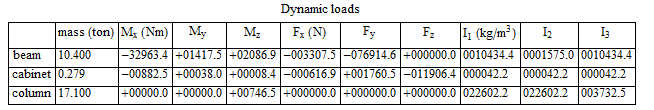
3.2.1 Summary of design input and design output
The following tables summarize the input and the output of the overall design. The tables list all the design
parameters and the meaning and usage of each. They show what is known at the start of the design and the
output from the design and simulation
The following table shows the output of the design based on the above input. Simulation was used to find an
optimal set of input parameters in order to achieve the customer specifications
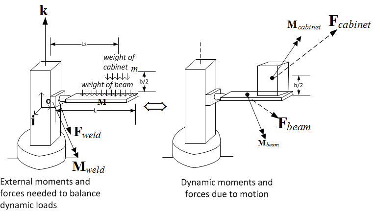
3.2.2 System dynamic loads and free body diagram
Before starting the derivation, the following two diagrams are given to show the dynamic loads to be
balanced with constraint forces. Two free body diagrams used. One for the beam and one for the
column.
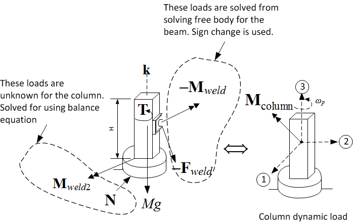
After  and
and  are solved for, they are used (with negative signs) as known constraint
forces on the column in order to solve for the column's own constraint forces and any external loads.
The free body diagram for the column is given below
are solved for, they are used (with negative signs) as known constraint
forces on the column in order to solve for the column's own constraint forces and any external loads.
The free body diagram for the column is given below
The analysis below shows all five derivations. The first obtains  (dynamic moment to rotate the
beam) using Euler method. The second finds
(dynamic moment to rotate the
beam) using Euler method. The second finds  (dynamic moment to rotate the cabinet) using Euler
method, the third uses Newton method to find linear acceleration of center of mass
(dynamic moment to rotate the cabinet) using Euler
method, the third uses Newton method to find linear acceleration of center of mass  (dynamic force to translate the cabinet), the fourth finds the linear acceleration of the center of
the beam and
(dynamic force to translate the cabinet), the fourth finds the linear acceleration of the center of
the beam and  and the final derivation finds
  (dynamic moment to rotate the
column).
(dynamic moment to rotate the
column).
3.3 Beam to column analysis
3.3.1 Finding  (beam dynamic moment)
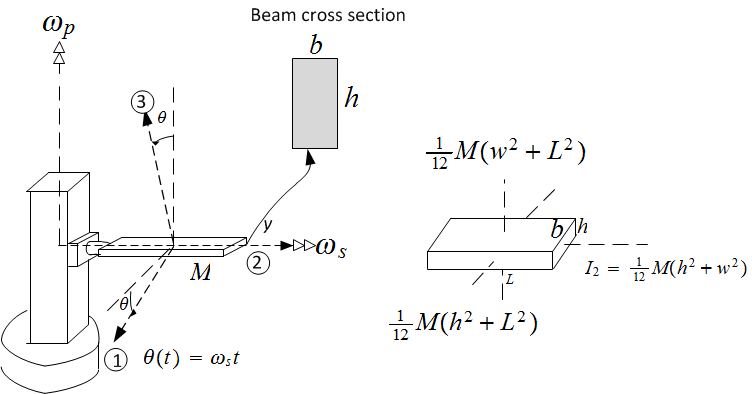
The platform is modeled as a rectangular beam. Its principal moments of inertia are given below.
Let  be the absolute angular velocity of the local body rotating coordinates
  . Let
. Let  be the beam
(the body) absolute angular velocity. Hence
be the beam
(the body) absolute angular velocity. Hence

But  , therefore
In component form
Taking time derivative
In component form
The moments of inertia of the beam using its principal axes at the center or mass are
Since  (center of mass is used as reference point) then

Moments of inertia cross products are all zero since principal axes is used. The relative angular momentum of the
beam becomes

The rate of change of the relative angular momentum of the beam using Euler equations is

Therefore, the moment needed to rotate the beam with the angular velocity specified is

The above components are expressed using in the beam body fixed coordinates system  (which is the
same as
(which is the
same as  in this case). These are converted back to the
  coordinates system using the following
transformation
coordinates system using the following
transformation
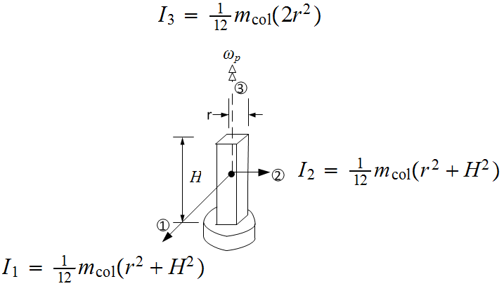
3.3.2 Finding  (column dynamic moment)
The main support column has one degree of freedom as it only spins around its  axes with
angular velocity
axes with
angular velocity  . Its center of mass does not translate in space. The column has a square cross
section. Its height and sectional area were fixed in the design to allow changing the beam and
cabinet parameters freely and see the effect on the joint stresses between the beam and the column
as the failure point in the design was considered to be the the joint between the beam and the
column
. Its center of mass does not translate in space. The column has a square cross
section. Its height and sectional area were fixed in the design to allow changing the beam and
cabinet parameters freely and see the effect on the joint stresses between the beam and the column
as the failure point in the design was considered to be the the joint between the beam and the
column
This is a case of one body rotating around its own axes. Therefore,

Where
Where  is the mass of the column. Hence

3.3.3 Finding  (cabinet dynamic moment)
The passengers including the cabinet are modeled as solid cube rigid body. The cabinet and the beam
rotate with the same absolute angular velocity and act as one solid body. They were analyzed
separately as it is easier to find the moment of inertias of each body separately than if both were
combined.
The center of mass of the cabinet is at a distance  above the beam where
  is the width of cube which is
the same as the beam width.
is the width of cube which is
the same as the beam width.
Since the cabinet is attached to the platform and is a rigid body as well, the same exact analysis that was
made to the beam above can be used for the cabinet. The only difference is that the moments of inertia  are different. In this case they are

Therefore, the body dynamic moments are
The above components are expressed using the cabinet own principal axes coordinates system  (local
body coordinate systems) which is its principal axes in this case. These are converted back to the
(local
body coordinate systems) which is its principal axes in this case. These are converted back to the  coordinates using the same transformation used for the beam
3.3.4 Finding  (cabinet dynamic linear force)
To find  for the cabinet, Newton method is used as follows
The rotating coordinates system  has its origin at the beam column joint.
  is attached to the
column and rotates with the column with angular velocity
is attached to the
column and rotates with the column with angular velocity  . The center of mass of the cabinet shown above
as the circle
. The center of mass of the cabinet shown above
as the circle  , is at distance
  from the origin
All calculations are expressed using unit vectors of the rotating coordinates system and are valid for
all time. In the rotating coordinates system, point  the center of mass of cabinet, appears as shown
in the following diagram. In this diagram
the center of mass of cabinet, appears as shown
in the following diagram. In this diagram  is the angle
  makes with the
  axes, where
  and
and 
Using the above diagrams, the absolute velocity of  is found as follows
Hence the absolute velocity of  is
is
The absolute acceleration of  is found from
Therefore the absolute acceleration of the passenger is
Simplifying gives
The above is expressed using the common  rotating coordinate system
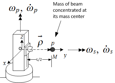
3.3.5 Finding  (beam dynamic translational force)
The linear acceleration of the center of mass of platform, which is located at distance  from the
origin
from the
origin  of the
  rotating coordinates system.
Therefore
Hence
Therefore
The above is expressed using the  rotating coordinates system.
3.3.6 Using free body diagram and solving for constraint forces
The dynamic forces have been found from above. The are balanced with constraint forces and
any external loads using free body diagram. The following diagram shows the balance between
dynamic forces and moments and external forces.  below is used to represent all constraint
moments at the joint between the beam the column, including the extra torque needed to rotate the
beam
below is used to represent all constraint
moments at the joint between the beam the column, including the extra torque needed to rotate the
beam
Taking moments at point  , the left end of the beam which is the origin of the rotating coordinates system

Hence

The force vector at the joint is
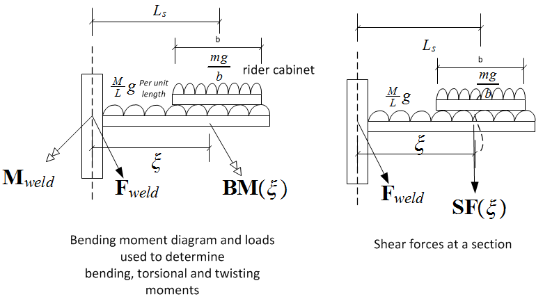
Bending moment and shear force calculations Now that the constraint forces are solved for from the
above analysis, the bending moment and shear force diagram are formulated. The moments will be a function of
distance from the beam/column joint.
Let  be the moments vector at distance
  along the beam length. There will be 3
components to this moment. Bending
along the beam length. There will be 3
components to this moment. Bending  , torsional
  and twisting
  .
.
Let the weight be per unit length of the beam which is be
be  . In the following, the notation
  is
used to indicate that the term is effective only when
is
used to indicate that the term is effective only when  is positive. Let the distance to start of the cabinet
be
is positive. Let the distance to start of the cabinet
be
 Where
Where  is the width of the cabinet.
 In component form, the bending moment will be
  and The torsion moment will be
  and
the twisting moment will be
and
the twisting moment will be  Let
Let  be the shear force vector at distance
  . Hence
 The above completes the mathematical derivation of the dynamics of the system. The next
step is to implement this model and use simulation to validate it and design for an optimal set of
parameters.
Finding shear and direct stress from bending and shear forces The result of the above
calculations is the moments and forces at the joint between the beam and the column and using
The above completes the mathematical derivation of the dynamics of the system. The next
step is to implement this model and use simulation to validate it and design for an optimal set of
parameters.
Finding shear and direct stress from bending and shear forces The result of the above
calculations is the moments and forces at the joint between the beam and the column and using  and
and
 at any other section in the beam.
The next step is to use these to obtain complete description of stress state at the section. Due to lack of time
finite element analysis was not performed. Therefore, basic beam theory equations were used for stress
calculation. Care was taken to insure that the beam cross section selected had thickness not less that
its width. Having a thin beam would require analysis using plate theory making it much more
complicated. The disadvantages of this method is that the beam was much heavier than needed if thin
beam was used, but the advantage is that the stress equations used are known to be valid in this
case.
Given the moments
at any other section in the beam.
The next step is to use these to obtain complete description of stress state at the section. Due to lack of time
finite element analysis was not performed. Therefore, basic beam theory equations were used for stress
calculation. Care was taken to insure that the beam cross section selected had thickness not less that
its width. Having a thin beam would require analysis using plate theory making it much more
complicated. The disadvantages of this method is that the beam was much heavier than needed if thin
beam was used, but the advantage is that the stress equations used are known to be valid in this
case.
Given the moments  and the forces
  all the cross section, the following equations were
used. These equations assume a rectangle beam cross section of thickness
all the cross section, the following equations were
used. These equations assume a rectangle beam cross section of thickness  and width
  and that
 Torsional stress was not fully developed in this design since it is a rectangular cross section and would require
finite element analysis. The beam is expected to fail due to bending moment
Torsional stress was not fully developed in this design since it is a rectangular cross section and would require
finite element analysis. The beam is expected to fail due to bending moment  and this is what the rest of the
analysis address. Future analysis of stress concentration will use finite element analysis and will take torsion
stress into account.
and this is what the rest of the
analysis address. Future analysis of stress concentration will use finite element analysis and will take torsion
stress into account.
3.4 Column dynamic analysis
In the above section the constraint forces in the beam/column joints were found. These are now used as external
forces on the column with an opposite sign. Free body diagram is used for the column in order to find the
constraint forces and external loads acting on the column. The following diagram shows the free body diagram
used
Taking moments at the joint between the column and the ground

Solving for the unknown constraint force  and the external torque

The torque  is unknown at this stage and has to be determined by other means to obtain complete solution.
This is the external torque needed to accelerate the column during ramp up and to decelerate it during
ramp down phases. Combining all the unknowns into one term called
is unknown at this stage and has to be determined by other means to obtain complete solution.
This is the external torque needed to accelerate the column during ramp up and to decelerate it during
ramp down phases. Combining all the unknowns into one term called  , the above reduces
to
, the above reduces
to

The balance equation for forces gives
Now that all loads acting on the column are found, bending moment and shear force diagrams can be also be
made or finite element analysis used in order to determine the stress state inside the column at every
section.
4 Simulation of the dynamic equations found
4.1 Review of the simulation
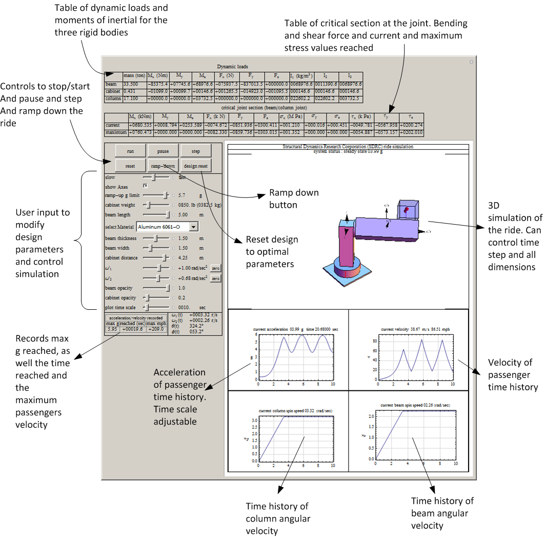
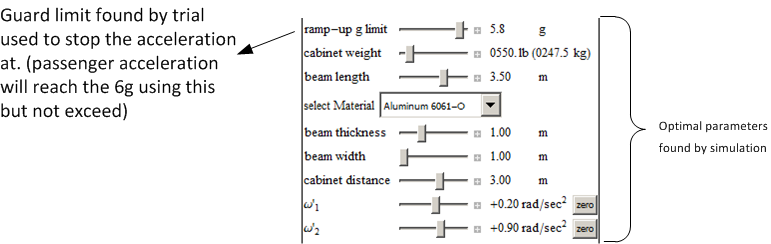
The simulation accepts as input all the parameters shown in table 1 on page 9. The goal of the simulation is to
verify visually the dynamics and to allow the selection of correct sizes for the structure and to insure that the
acceleration does not exceed  using the selected parameters. Based on the simulation, one optimal set of
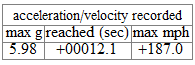
values was selected and given in the conclusion section. The simulator displays tables showing all the current
values for stress and moments found at the beam/column joint. It keeps track of the maximum
stress values reached and uses these to determine the maximum stress using the equations shown
above.
using the selected parameters. Based on the simulation, one optimal set of
values was selected and given in the conclusion section. The simulator displays tables showing all the current
values for stress and moments found at the beam/column joint. It keeps track of the maximum
stress values reached and uses these to determine the maximum stress using the equations shown
above.
This diagram shows an overview of the user interface. This software can be run from the project
web site located at http://12000.org/my_notes/mma_demos/EMA542_project/index.htm
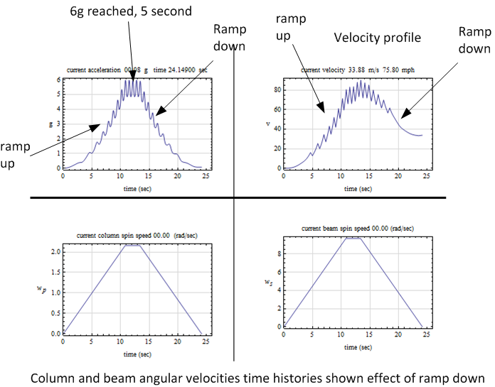
4.2 Simulation output, time histories and discussion of results
All these tables and results below are generated from the final design using the selected final optimal
parameters.
4.3 Discussion and analysis of results
The following table gives the optimal design parameters found by simulation of the derived model in order to
achieve the customer requirements.
It was found that in order to be able to achieve the  limit and not exceed it, the acceleration have to put
turned off well before the
limit and not exceed it, the acceleration have to put
turned off well before the  is detected. This can be seen by examining the passenger acceleration expression
from above, which is
is detected. This can be seen by examining the passenger acceleration expression
from above, which is
We can see that, by letting  and
and  then the acceleration becomes

Even though from now on the angular velocities  and
and  are constant, this does not imply that
  will
become constant. Since
will
become constant. Since  is still changing in time, then
  will still fluctuate in periodic fashion from now on.
Hence the passenger acceleration can still exceed
will still fluctuate in periodic fashion from now on.
Hence the passenger acceleration can still exceed  if we were to turn off the ramp up acceleration too close to
 . For this reason the value the acceleration was turned off at
  in order to final value of
  as felt by
the passengers.
as felt by
the passengers.
4.4 Cost analysis
Based on the above result and using the mass needed, the following table gives a summary of cost for
construction of the ride
The major part of the cost is for material. This is due to the use of thick beam and column.
This allowed the use of basic beam theory stress analysis. This cost however can be reduced by
the use of plate theory or numerical finite elements methods in order to be able to safely used
less material and reduce the thickness of the beam and column while insuring accurate stress
calculations.
5 Conclusions of results and future work
The final design given above meets the requirement specification that the customer provided. Using simulation, it
was possible to validate the equations found and to confirm that the beam/column section is safe for the selected
optimal parameters.
The selected parameters allow the passengers to reach almost  in
in  seconds using a ride that consist of
two noncollinear angular velocities. There are many different profiles that could have been selected to achieve this
goal. The set selected reached the closest to
seconds using a ride that consist of
two noncollinear angular velocities. There are many different profiles that could have been selected to achieve this
goal. The set selected reached the closest to  without crossing over and that is why it was selected. The
following is the final design used
without crossing over and that is why it was selected. The
following is the final design used
The cost estimate is $79,800. The material cost was the major part of this cost. This was
due to the use of simple beam theory for stress analysis equations which required the use of a
thick beam in order for the stress equations to be valid. The maximum stress of  MPa reached is well below the yield strength of Aluminum. Therefore, the use of finite element
stress analysis or advanced plate theory would have allowed the reduction of the size of the beam
while at the same time using accurate stress calculations. This would have resulted in lower cost
in material. If awarded this contract, finite element would be used in order to lower the cost of
material.
MPa reached is well below the yield strength of Aluminum. Therefore, the use of finite element
stress analysis or advanced plate theory would have allowed the reduction of the size of the beam
while at the same time using accurate stress calculations. This would have resulted in lower cost
in material. If awarded this contract, finite element would be used in order to lower the cost of
material.
5.1 Future work and possible design improvement
The following are items that can be improved in the current design given additional time to perform
-
1.
- The beam and column weight can be reduced significantly by using plate shell stress analysis. This
should reduce the material cost. This design used simple beam theory stress analysis which required
the use of thick beam. This caused the beam to become too thick. It will be possible to have thinner
beam and still not reach the yield strength. Using finite element method will allow this investigation.
-
2.
- There are additional possible cross sections to consider for failure analysis. This design concentrated
on the most likely section based on beam theory. Using finite element software will allow one to
more easily analyze the full structure more easily than was done in current design based on simple
beam theory.
-
3.
- Torsional and twisting stress analysis were not addressed in this design due to time limitation. It is
however expected that the beam will fail in bending.
6 Appendix
6.1 Use of simulator to validate different design parameters
These are selected screen shots showing different configurations tested during simulation in order to
find an optimal one. These show the effect of changing the dimensions of the structure and the spin
rates.
6.2 References
-
1.
- Daniel C. Kammer, EMA 542 lecture notes and printed book. University of Wisconsin, Madison.
2013
-
2.
- R. C. Hibbeler. Engineering Mechanics, Dynamics. Prentice Hall, NJ 2011
-
3.
- Aluminium page at Wikipedia http://en.wikipedia.org/wiki/Aluminium
-
4.
- Moments of inertia page at Wikipedia http://en.wikipedia.org/wiki/List_of_moments_of_
inertia
-
5.
- Density of materials page http://physics.info/density/
-
6.
- Beam design formulas with shear and moment diagrams book, AWC council, 2007, Washington,
DC.


 ,
,  GPa, Max tensile 125 MPa, Max yield strength 55 MPa


 lbs per person, total of two persons including additional
  lbs for seats

 g
g 
 MPa
MPa 


 of tensile yield stress


 m.p.h.
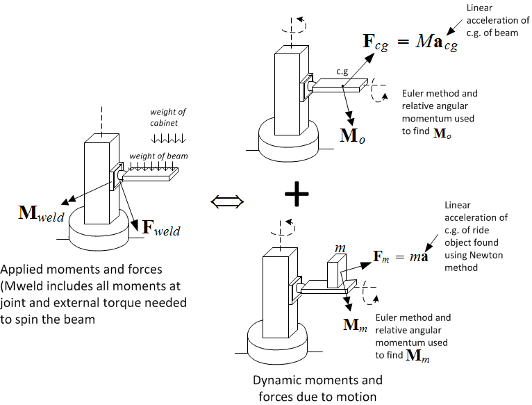


 used to find passenger acceleration
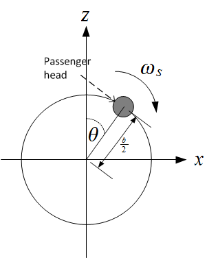


 used to find beam center of mass acceleration


 felt by passenger to insure it does not exceed
 ton
ton  meters
  meters
  meters
  lbs
lbs  meters
  meters
  ton
ton  by
by  meters
 KNm
KNm 
 KNm
KNm 
 KNm
KNm 
 KN
KN 
 KN
KN 
 KN
KN 
 MPa
MPa  MPa. and
 MPa
MPa  MPa.
MPa. 
 MPa
MPa 
 KPa
KPa 
 KPa
KPa 
 KPa
KPa 


 reached

 sec.
sec.  m.p.h.
  reached
  rad/sec.
  reached
  rad/sec.
 rad/sec.

 rad/sec.

 rad/sec.

 rad/sec.